40 amp to 160 Amp - Diversion Controller
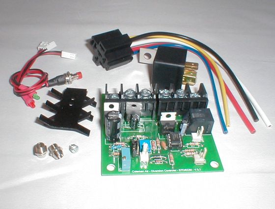
**** Completed Circuit Board with one 40 amp Relay ****
12v or 24v Systems
This item is for the COMPLETED CIRCUIT BOARD with no enclosure
Below is a description of the complete charge controller - this Item does not contain the enclosure and it has one 40 amp relay only - not 4 relays.
Please see our other listings if you would like to purchase the completed controller.
This diversion controller is the result of our many attempts to use the controllers currently on the market (offered by some of the largest names in the business), to work in conjunction with our wind turbines. None of the other diversion controllers on the market did what we needed a diversion controller to do. So we designed our own -- and added all of the features that are truly needed in a diversion controller.
Some of the key features of this controller are:
- Microprocessor controlled -- This is very important for both stability and functionality.
- User changeable settings -- Several controllers on the market set the dump level, and that's that!
- High amp rating - 160 amps with the 4 relays installed -- You may add more if you actually need more amps.
- Battery status LED - Several controllers do not tell you what's going on - This one does!
- Push to test. Ever wonder if your controller & load are working OK?
- Steel enclosure, with two conduit openings.
- Large enough terminal blocks that you can actually terminate large wire (See notes below.)
- Super large heat sink -- Pulling in multiple relays takes energy - which generates heat. This one handles it!
- RJ-11 Serial interface. --This allows connection to a computer for both programming and remote status (See notes below.)
- Can divert the source from the batteries to the load, or dump both the batteries along with the source.
Some specifics about the points made above.
The microprocessor is the heart of the controller. It is given the battery voltage and the user changeable trip points. This information is analyzed and acted upon.
The Battery level is checked, and based on that info, the Green LED flashes or is illuminated as follows
- (One) Flash indicates the battery is less than 12 volts (12 volt system - Double for 24 etc)
- (Two) Flashes indicates the battery is 12 to 12.5V
- (Three) Flashes indicates the battery is 12.6 to 13v
- (Four) Flashes indicate the battery is 13.1 to 13.5V
- ( Five) Flashes indicates the battery is above 13.5V but less than 13.9V (Settings are adjustable)
Steady green means the battery is full.
The red LED is illuminated when the battery is being dumped at 14.5v (or the charge source diverted.)
The dump remains active for a min. of 5 seconds, at which time it is checked by the microprocessor. If battery voltage drops below the "Dump Cancel " level, the dump is disabled, otherwise the dump is continued and rechecked every 5 seconds.
When you click the "TEST" push-button - the 5 second cycle is started (one time, unless the batteries are within the "Dump start" and "Dump Cancel" zone.)
Settings are user changeable!! By simply turning a simple potentiometer with a small screwdriver, you can quickly adjust the trip point.
If you are a DIY type of person, you can modify the program directly -- it will do whatever you program into it!
High amp rating -- 160 Amps as configured! -- This is a big controller.
There is nothing stopping you from adding more relays for nearly an unlimited amount of load capability.
The following precautions must be taken into account if you wish to add more relays.
The internal regulator can handle 12 relays (40 amp automotive type) in a 12 volt system and 4 relays in a 24 volt system. The reason for the smaller number of relays in a 24v system is the regulator must convert the high battery voltage down to 15 volts for the relay coils, this generates heat. So if you want to add more relays than 4 (or 12), then simply use one of the relays to switch on the coils of the other relays. This will allow you to pull in as as many relays as your wire can handle.
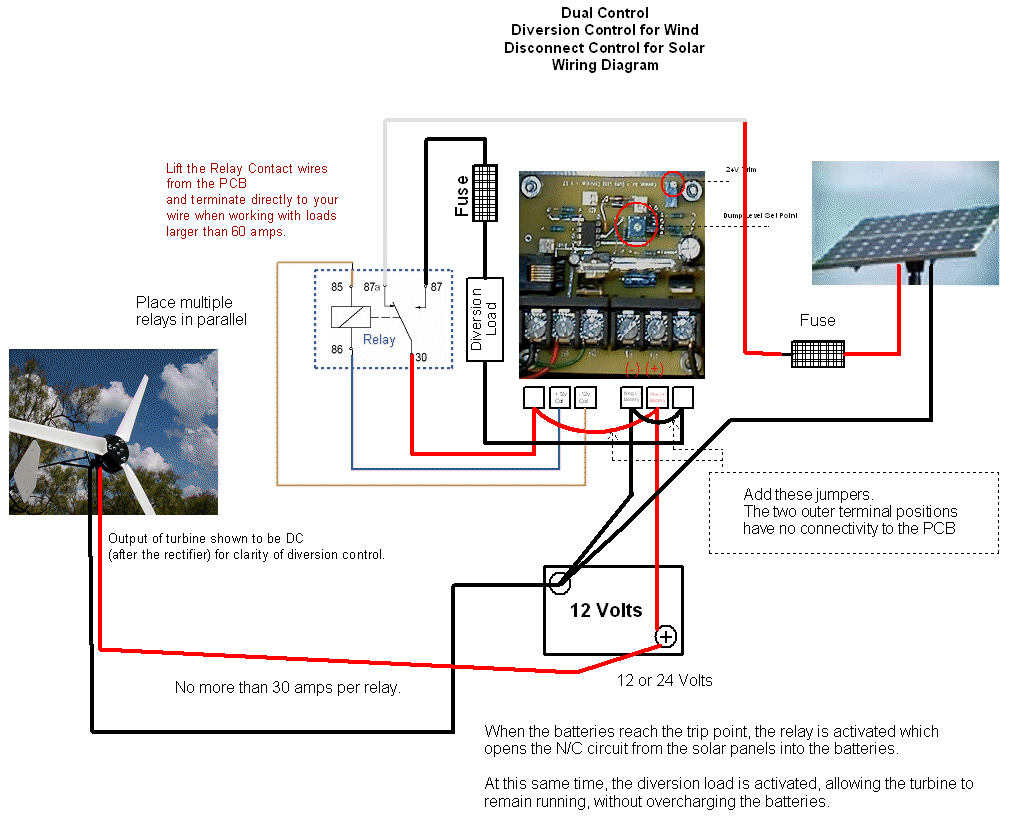
About wire size -- 160 amps is a lot of current! -- The terminal blocks inside the case will handle #8 wire and are better used for switching loads of 60 amps or less. If your system will likely run at the high end, then a better connection is to simply remove the two relay contact wires from the internal terminal blocks and terminate them to your larger wire directly via a wire nut, or compression lug etc.
The enclosure is heavy gauge, solid steel - Ready to mount. -- No plastic, no junk, simple and rugged.
About load diversion.
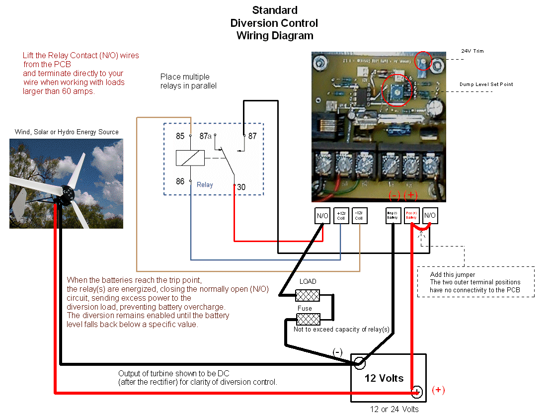
The basic operating philosophy of a diversion controller is quite simple. Monitor the battery voltage, and if it should rise to a predetermined level, connect a diversion load (or "Dummy Load"), of sufficient size, to the battery or energy source to prevent the battery voltage from increasing any further. This is a very simple, yet very effective way of preventing battery overcharging. All alternate energy systems should have some form of battery overcharge protection.
Several schools of thought on the subject.
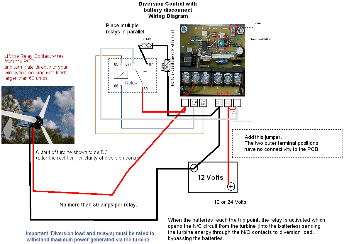
- The source of power (wind turbine, solar panels etc.) -- should remain connected to the batteries while the dump is active.
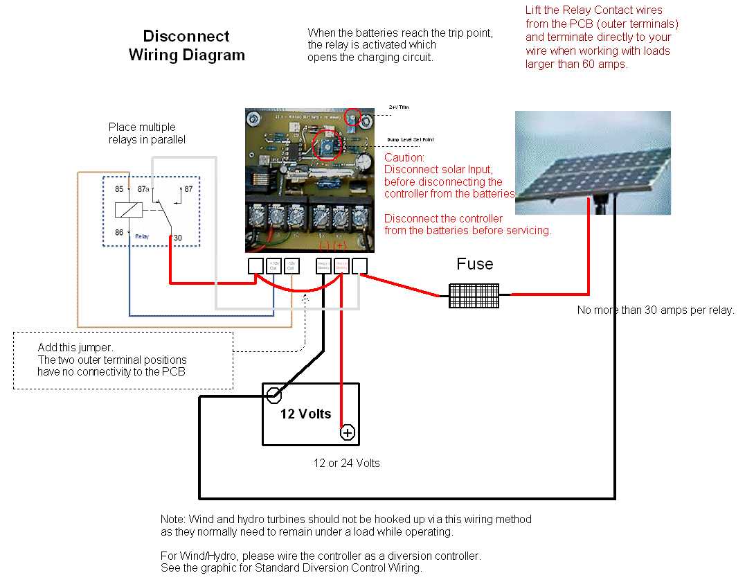
- The source should be diverted to the load directly and disconnected from the batteries.
We happen to believe that is far better to leave the wind turbine connected to the batteries at all times. Why? When you remove the battery level voltage from a wind turbine and send it's power directly to a load, then it sees for all practical purposes a short circuit (depending on the resistance of the load and lead wires.) This may cause the turbine blades to slow dramatically and in some cases bring it to a halt. This braking action can cause heat build up in the stator if it is repeated every few seconds or so (if the battery is just a little over the top). When you allow the turbine to see the batteries, along with the load, the turbine remains more within it's design realm -- always a good thing.
The internal relays are configured to dump the batteries along with the source, but if you desire to disconnect the source from the batteries and send it to the load directly, simply utilize the N/C contacts of the relays as well. We'll be happy to send you a diagram -- this is a very simple change.
How to compare this controller to others on ebay (or anywhere!)
-
Do they have battery status indication?
-
Do they have a dump active indication?
-
Are the dump levels user changeable?
- Are they microprocessor controlled?
- Do they come with a enclosure that's actually ready to use?
-
Can they truly pull in multiple relays without burning up or do they need fans?
-
Do they handle the amperage you need?
-
Do they have a dump test capability?
-
Can they be hooked up to your PC?
-
Do they include the program and circuit schematics?
When you compare this controller to the others, you will see why we built it and why we know you'll love it.
THIS Item IS FOR THE ASSEMBLED CIRCUIT BOARD without enclosure
Please note: The above text talks about the fully completed charge controller with enclosure. THIS Item IS FOR THE CIRCUIT BOARD ONLY AND INCLUDES THE FOLLOWING ITEMS --- ONLY.
- Completed, tested and calibrated circuit board.
- 1 green LED wired to the PCB connector
- 1 red LED wired to the PCB connector
- 1 pushbutton wired to the PCB connector
- 1 12v - 40 amp relay with wire harness
- Manual
**** NO ENCLOSURE IS PROVIDED ****


