|
ITS-240
Inverter Transfer Switch
For:
240 Volts A/C, Split phase
and 120 Volts A/C inverters.
12/24/48v Systems
The Coleman ITS-240 Inverter Transfer Switch
Hookup Diagram
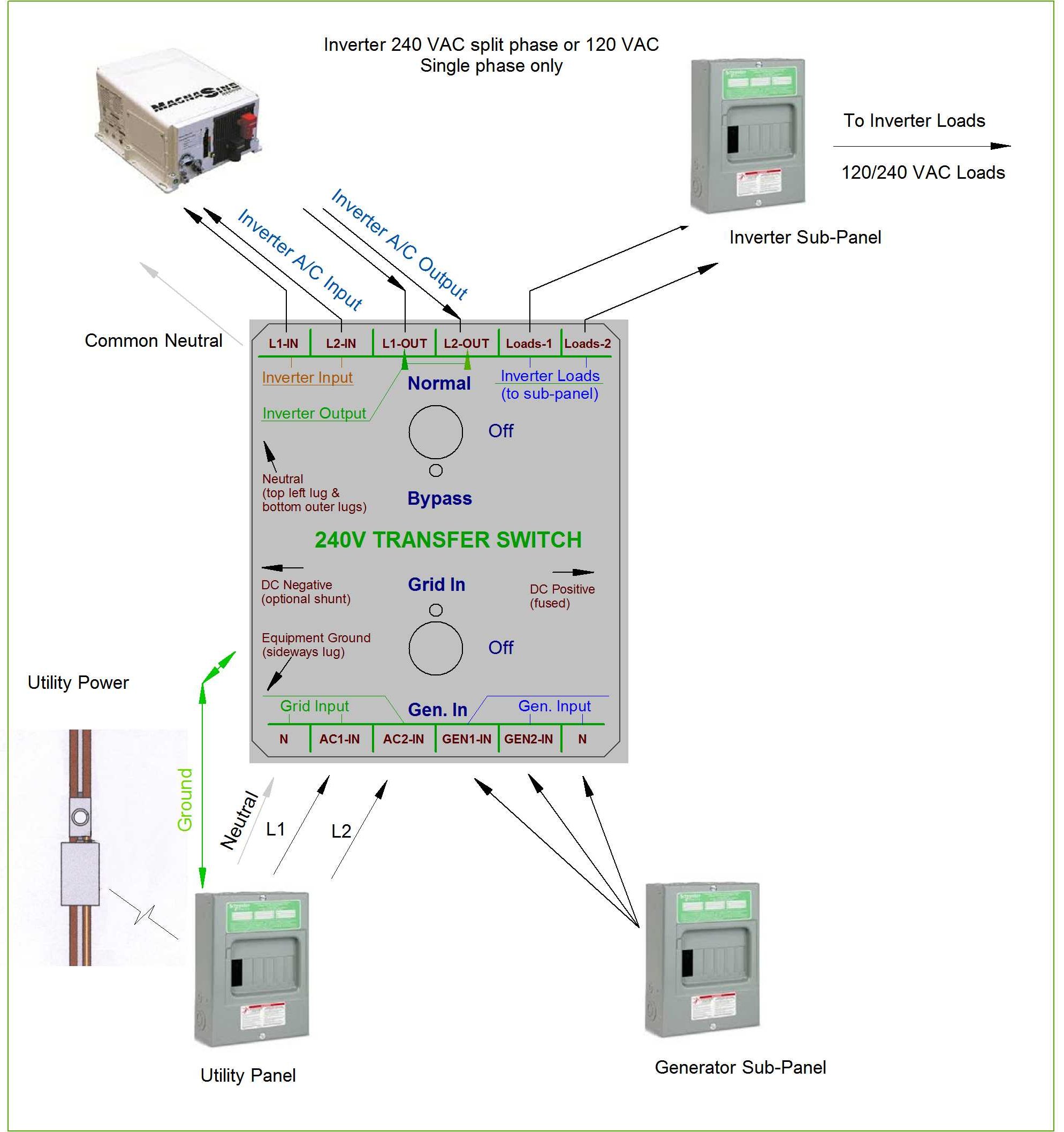
Typical A/C Wiring.
This diagram shows using the switch with a 240V A/C Split phase inverter.
The Coleman Air Inverter Transfer Switch has been designed to solve the wiring complexities of inverters having a grid input capability for both split-phase 240 VAC and/or standard 120 VAC inputs and outputs, all in a single compact electrical enclosure. The switch also offers stand-offs for both a D/C fuse as well as a D/C shunt to be used with an optional D/C amperage meter.
Some of the key featuresof this controller are:
- ·Super simple wiring that solves complex input/output requirements of advanced inverters.
- ·Two switches fully handle the selection of both the A/C input source as well as the A/C output source.
- ·Especially designed for inverters having built in battery chargers.
- ·Allows for the selection of either Grid Input, Generator Input, or no A/C input.
- ·Allows for the selection of either Inverter A/C output, Grid/Gen. A/C output or no A/C output.
- ·Includes a 200 Amp ANL/ANE D/C fuse, with two 1/0 Lugs for fusing the DC positive wire. (You may specify a different value fuse when ordering.)
- ·Offers a location for a standard 75mv - 100 or 200 amp shunt for an optional Coleman Air amp meter.
- ·Safe and secure, fully enclosed, no exposed wiring once the lid is enclosed.
- ·Fast and easy installation using a standard enclosure with multiple knockouts available.
- ·Capable of handling 15 amps per leg A/C input and output for inverters up to 7200 watts continuous.
- ·Capable of mounting ANL D/C fuses up to 400 Amps.
- ·Perfect for inverters not having separate generator input terminals.
Specifications:
- 30 amps max per A/C leg.
- 7200 watts total continuous capacity for 240 VAC inverters.
- 3600 watts total continuous capacity for 120 VAC inverters.
- Common neutral on all inputs and outputs.
- A/C input/output terminals handle 6 AWG wire.
Stainless steel standoffs included for 75mv shunt.
Enclosure dimensions:
- 8.25 (width) x 12.25 (height) x 4 (depth).
- 4 mounting holes, with threaded ground hole and ground lug.
- Non locking, hinged lid.
- Enclosure is UL Certified.
Cautions:
The electrical lines to and from an inverter and this switch can be LETHAL!
Disconnects should always be used that do not require you to open a box or enclosure to activate or disengage.
Ensure you have selected an adequate size wire for the amperage you will be switching.Undersized wire can result in high heat build up in the wire and connections possibly leading to a fire. Use extreme caution when installing or servicing this switch. Always disconnect the energy source before servicing this unit.
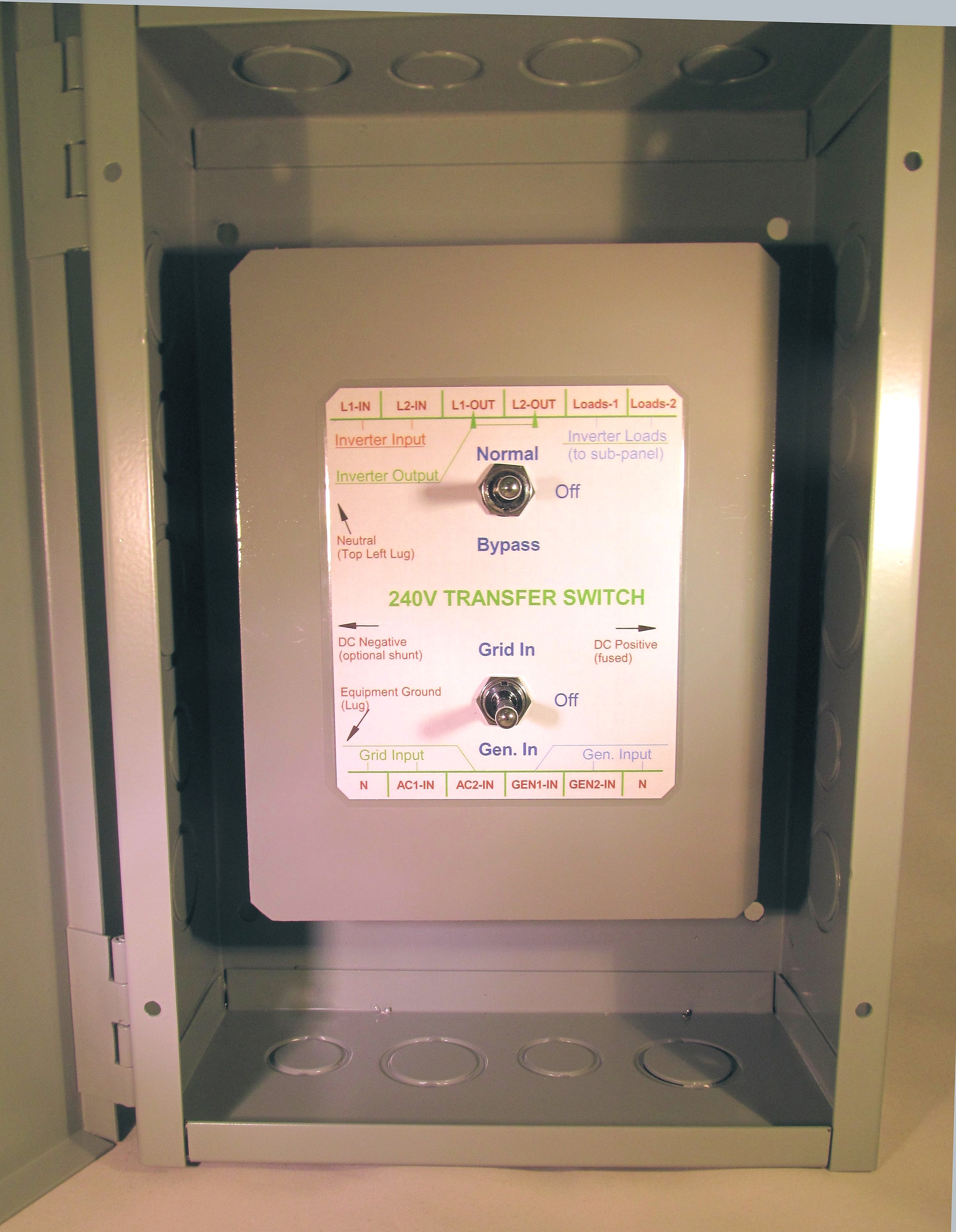
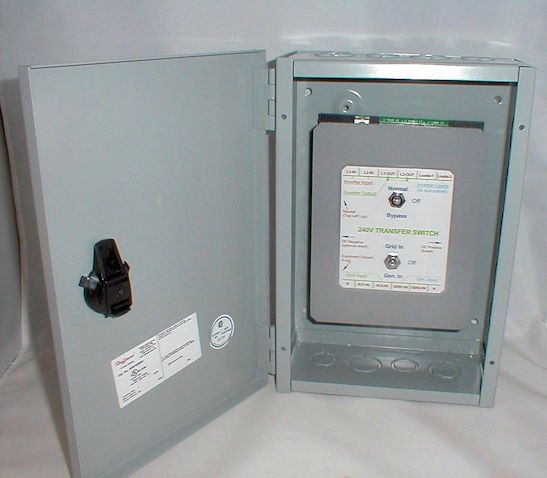
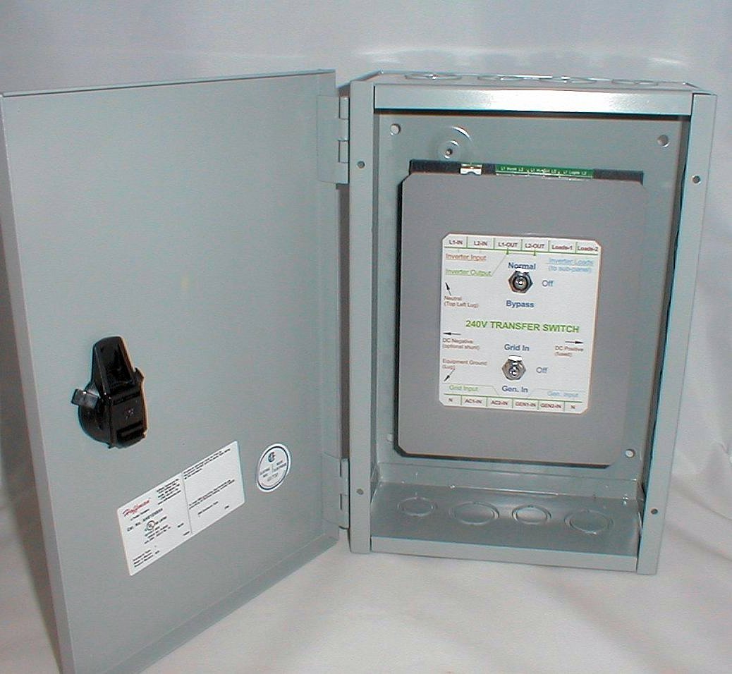
Coleman Air ITS-240 Inside Zoom
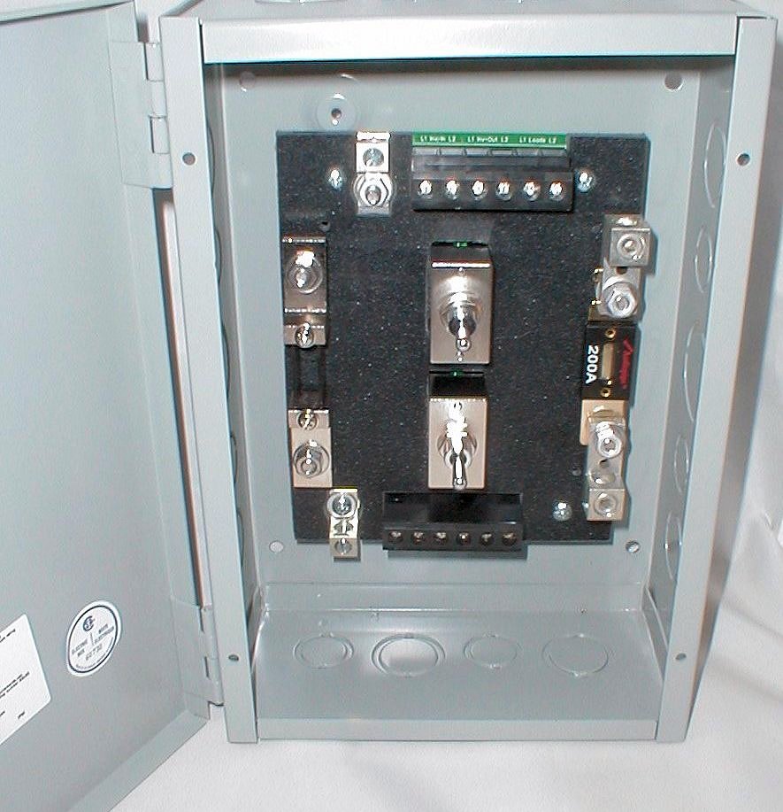 Coleman Air ITS-240 (Shown without the protective cover) Note: The optional 200 amp shunt mounted on the left, for use with an external amp meter. Also shown is a 200 amp fuse (right side) -- Please specify the amperage fuse you would like if different.
Switch Settings
The three-position top switch controls the A/C output source to the A/C loads.
·Normal position (switch up) sends the inverters A/C output to the A/C load terminals.
·Off position (switch in the middle position) turns the A/C output off (no power to loads.)
·Bypass position (switch down), sends the A/C grid or A/C generator to the A/C loads.
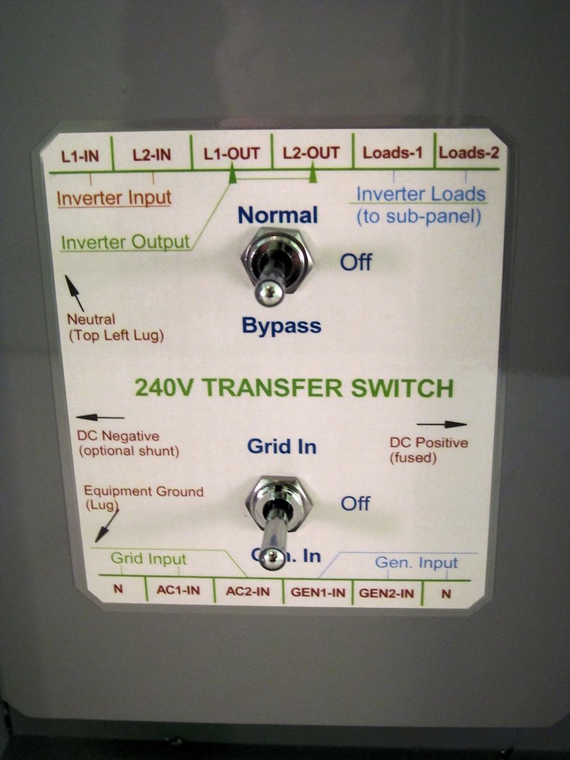
The three-position bottom switch controls the A/C input source.
·Grid In position (switch up), allows the grid connections to be routed to the inverters input.
·Off position (switch in the middle position), turns off all A/C input to the inverter.
·Generator In position (switch down), allows the generator connections to be routed to the inverters standard A/C input terminals.
Many inverters today have built in battery chargers. These chargers are very powerful and convenient tools to ensure your batteries remain charged during low solar/wind days, yet on a normal basis, these chargers are often not required as there may be sufficient input of alternate energy, and it is this energy that most owners wish to employ. The problem is the internal charger often runs as a priority event always charging the battery, not allowing the solar/wind energy to be the primary source. Often inverters internally switch to the their bypass mode anytime there is a qualified A/C input available sending the external A/C input directly to its output terminals essentially placing the inverter in a standby mode at all times. While this is a nice feature when needed, it completely removes any advantage of having solar/wind power available on a normal basis if it is seldom used.
 This switch easily accommodates this situation, allowing you to turn on or off any A/C input into the inverter, forcing the inverter to use its normal Inverter mode, by drawing power from the batteries and converting it to A/C power to send to the connected A/C loads. When an event does occur where there is not enough solar/wind energy to maintain the batteries, then simply turning the A/C input back on to the inverter re-enables the built in inverter A/C features, and the inverter will switch back its internal bypass mode and begin to charge the batteries as well. This switch easily accommodates this situation, allowing you to turn on or off any A/C input into the inverter, forcing the inverter to use its normal Inverter mode, by drawing power from the batteries and converting it to A/C power to send to the connected A/C loads. When an event does occur where there is not enough solar/wind energy to maintain the batteries, then simply turning the A/C input back on to the inverter re-enables the built in inverter A/C features, and the inverter will switch back its internal bypass mode and begin to charge the batteries as well.
Please note: Inverters charge and bypass modes vary from model to model. The above scenario my not be applicable to your inverter.
Another feature of this switch is to allow the A/C input (either grid or generator), to be sent directly to the output terminals. This is especially useful if the inverter has failed or needs to be serviced. By switching the top switch to the bypass mode, the inverters outputs are no longer required to power the loads. This is also very handy for inverters that do not have built-in chargers, and the batteries are low and the A/C loads need to be powered directly from the grid or generator.
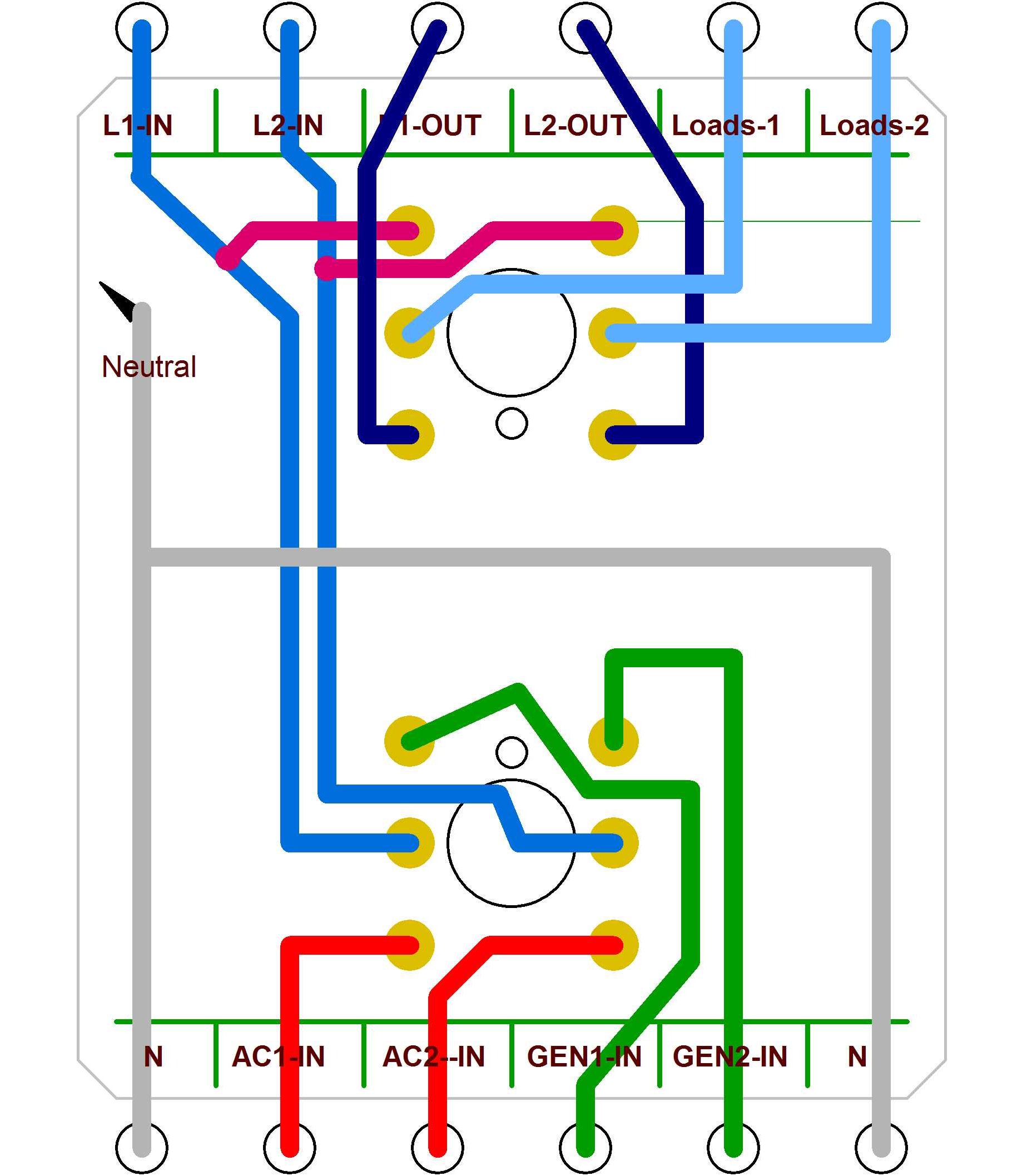
The drawing left shows the internal wiring of the ITS-240 switch.
Note: Wires on the bottom of a switch are connected to the middle of the switch when the switch is in the upper position. For example, the red wires are connected to the blue wires (bottom switch), when the switch toggle is in the up position.
The bottom switch is designed to accommodate inverters that do not have separate generator input terminals. When the bottom switch is in the upper position, the A/C input on the bottom left terminals is sent to top switch. When the bottom switch is in the lower position, the A/C inputs on the bottom right terminals are sent to the top switch. When the bottom switch is in the middle position, no A/C input is sent to the top switch or inverter.
|